17 Dec 2016

Aerosol flammability

More danger, less safety? The new inflation of flammability warning symbols on Aerosol cans

It’s a helpful tool for every maintenance person, the aerosol can. They can bring it to each area of the plant to loosen bolts or lubricate equipment. During maintenance, it’s not unusual for sparks to fly (grinding or cutting metal pieces) or open flames to be present (welding or flame cutting). As a result, the safe choice for maintenance personnel was, until now, using an aerosol can, which is non-flammable.

How do I know how flammable my aerosol really is? Look at the small print on the label to find out how dangerous the aerosol can really be. This small print is available in all official EU languages. 


The Chesterton aerosol cans used in these applications were always, and still are, the safe solution:

-        723 Sprasolvo
-        723FG Sprasolvo
-        601 Chain Drive Pin & Bush Lubricant
-        651 Detergent Lubricant
-        610 Synthetic Lubricating Fluid

So, if the safety of your maintenance person is your priority, make sure you use the correct product.
Make sure it’s Chesterton.

Further information on the technical aspects of the product may be found on the Chesterton website or on the product data sheet, don't hesitate to contact us.


Ingo Stenner.  - Ingo.stenner@chesterton.com


New Marketing Coordinator for EMEA

Hello,

My name is Vitaly Igonin and I am glad to join the Chesterton family as a new EMEA Marketing Coordinator .

I am happy to share with Chesterton my marketing experience from other global industries  and to create the success together. Innovation technology, strong position on the market, great team and family tradition of Chesterton impress and encourage me in the daily and future challenges.

To give my background, I'm from a nice Russian city (Saratov), worked in Moscow and live since 5 years in Germany. During this period, I did a MBA International Management  in  Reutlingen, and worked for famous German companies Robert Bosch, Burda, SEW-Eurodrive and s.a.x. Software.

In my new function, I'll support the marketing and sales teams as our partners. This new challenge is very excited, and I hope to see you soon during our next trainings, exhibitions and events. Don't hesitate to contact me. I'll be glad to support you.


Vitaly
@ vitaly.igonin@chesterton.com


New Marketing Manager for EMEA

Just a few words to introduce myself, my name is Laurent Prunier-Duparge, and since June 2016 I’m the new Marketing Manager for EMEA. My team and I are working to support the sales organization across EMEA.

I have been working for Chesterton since 2010 and during this period I have become familiar with the Chesterton Culture. In Chesterton, the principle of “Customer First” is not only an idea but also a daily focus.
“Together we accomplish more” this moto used during our latest Sales Meeting summarizes the Chesterton philosophy with our Partners and Customers.

Our experienced team, Hans, Ingo, Nick, Paul, and Steven, with our new Marketing coordinator, Vitaly and myself are proud to support you in your business.


Laurent Prunier-Duparge
@ laurent.prunier-duparge@chesterton.com

Chesterton® 607 HTS Lubricating Fluid launch


In May 2016, we launched a new high performance, 100% synthetic oil, 607 HTS, that is designed to lubricate at high temperatures -30C to 250C (-22F to 482F).
It improves performance and increases productivity of your equipment by reducing wear, varnish, and corrosion.  This in turn improves reliability and reduces costs.
It is European Produced, REACh compliant, mid-range, lower List price version of our 610 Synthetic Lubricating Fluid family.
The new Chesterton® 607 HTS Lubricating Fluid is available in two viscosity grades

- 607 HTS-68 Lubricating Fluid – ISO VG 68
- 607 HTS-220 Lubricating Fluid – ISO VG 220


Laurent Prunier -Duparge
Laurent.prunier-duparge@chesterton.com


16 Dec 2016

Style 459: Graphite Sheet with Nickel Reinforcement


The EME market has focused on the availability of pre-cut gaskets and includes a number of different expanded graphite styles.
What are the difference between a gasket with stainless steel inserts (as the Duragraf types) and the 459 Gasket type?
The Duragraf is ideal to cut on a machine but are harder to cut by hand.

The Style 459 is a very popular product, is due to its excellent operating parameters and above all the ease that the gasket can be cut manually.

Style 459 is made from high purity expanded graphite and is reinforced with a 0,026 mm thick nickel flat reinforcement, when the Duragraf F is made with a 0,05 mm stainless steel flat insert (0,1mm for the Duragraf T)

Read more here

  • Easy to cut manually
  • Excellent pressure capability
  • High temperature & Chemical capability


Laurent Prunier - Duparge
Laurent.prunier-duparge@chesterton.com

The importance of stem seal configuration in ISO 15848-1 certified valves

Valve Test - Chesterton Lab (Groveland -MA)
There are many emission standards nowadays that apply to valves and it is difficult to keep track of all of these and to all understand them. Some examples of valve emission standards are the ISO 15848-1, the API 624 and the VDI 2440 standards. And besides these there are a number of standards that apply to seals only. What all of these standards have in common is that the stem seal is crucial for getting valves certified. But to get a stem seal to work correctly the design of the valve has to comply with  a number of requirements such as component strength, surface roughness and dimensional tolerances. As well the way of installing the seal is of great importance. The article gives an introduction to which factors are important to make a valve compliant. Modern emission requirements can be a challenge but by following a number of guidelines every valve manufacturer can be successful in bringing low emission valves to the market. Chesterton can be of tremendous help with this process because of the vast experience that we have already built in this field


Hans Dekker

hans.dekker@Chesterton.com

Senior Application Engineering at A.W. Chesterton Company and he is supporting the Stationary Equipment business segment in the EMEA region. Hans was the Chairman of the Packings Division for the European Sealing Association.

4 Jul 2016

Sealing large pumps, agitators and mixers with Split Mechanical Seals

Split mechanical seals are widely accepted in almost every industry and application. The chemical industry is convinced of the benefits of this seal on large rotating equipment systems and puts to use split seals, among others for agitators, mixers and pumps


Facts for operators


  1. Split mechanical seals are a reliable solution for sealing all large pumps, agitators and mixers.
  2. Their biggest technical advantage is the fast turnaround of plant availability and production: users can install the seals without equipment disassembly.
  3. The seals meet the requirements of the Atex and clean air policy and can be used universally.


Since their introduction in 1986 split mechanical seals are now commonly found in process industries around the world and are used to simplify maintenance tasks and reduce the associated costs. The chemical industry is convinced of the benefits of this type of seal on large rotating equipment such as agitators, mixers and pumps. Since then time has not stood still, and so manufacturers have developed since the introduction of the first generation numerous technical improvements with which the features and applications for split mechanical seals are greatly expanded: Split Seals initially found only in the simplest applications, such as industrial water pumps, today even in demanding applications in many industries as both single- as well as double-seal configurations.

Production instead of repair
The operating parameters of the present generation have been expanded to cover vacuum (711 mm Hg) up to about 35 bar (g). All split versions are ATEX certified and all double-acting versions are TA-Luft compliant. Shaft diameters available are from 25 to 300 mm. However, larger diameters are also not a problem: Seal manufacturer Chesterton for example provides split seals for water turbines up to 700 mm shaft diameter. The biggest advantage of a split seal, however, is that the conversion of the sealing point can be carried out without disassembling the equipment. Example is the 442C-seal manufacturer: One of the hallmarks of this seal is the use of split O-rings which are not glued and are at any time to re-open by the operator. Another important feature is the divided sliding surfaces reach their tightness by a special break and connection technology.

Applications: everywhere
Pressure balanced Face Geometry is a fundamental principle of the seal manufacturer, which is also used in Split Mechanical Seals to allow an even pressure distribution on the surface and thus a long service life. The ability of these split mechanical sealsto seal vacuum is made ​​possible by the shape of the seal faces and through the seat of the stationary O-ring, bringing operators the benefits in the form of a high universality of application areas. Outside springs keep the faces together, prevent rotation of the static seal ring and reduce the axial length of the seal so that it fits into tight spaces. A variety of other features enable fast and simplified installations such as the captured fasteners and fully tapped gland halves allowing the fasteners to be used in either gland half, and also the pre fitted spacers preventing the need for setting measurements.


The Author

Marcel Blagajski is Key-Account, OEM and Enduser Manager for Chesterton International GmbH

19 Apr 2016

Reliability of aging static equipment (2): Best practice for Flange Sealing

The majority of flanges in a modern process plant function without issues. However there are a number of flanges that cause major headaches.

Emergency Repaired Heat Exchanger Flange
A flange gasket needs a certain stress over a certain gasket width to be able to generate the pressure drop that is required in sealing a flange. This gasket stress needs to stay between a certain minimum and a certain maximum value. The gasket stress is generated by tightening the flange bolts to about 30-70% of their yield strength. The failure that can occur and make a flange leak have either to do with the fact that the sealing gap is not maintained or the fact that the sealing force falls under a certain minimum.
Gasket Stress

Bad flange surfaces, bad bolts or improper tightening of bolts are common causes of flange failure. If the flange condition is bad the flange should be replaced or repaired. Repair can be done by machining the flange or to coat the flange with a special coating. Large flanges can be machined in situ with special equipment.

Corroded bolts or plastically deformed bolts cannot perform their function properly and will not provide sufficient sealing force on the gasket. It is recommended to replace flange bolts at each gasket replacement. Live Loading can help to increase the elasticity and compensate for the effects created by thermal cycling, loss of gasket thickness and as well might compensate some of the issues that are the result of yielded bolts and bad bolt tightening.
Flange Live Loading Installation

Correct flange tightening values are derived from theoretical calculations. In the petroleum industry the method described in Section VIII of the ASME Boiler and Pressure Vessel Code is commonly used. In Europe EN1591-1 is winning ground to become a reliable method to calculate the ideal bolt force on circular flanges.

When a torque wrench is used at installation, it is important to use the lubricant with a K-factor or coefficient of friction that was used in the calculation.
Stud Lubrication

The correct stress should be established on the entire surface of the gasket. Thus all bolts should be tightened simultaneously or successively by using a tightening method that gradually build up the stress in a cross pattern. This is done by applying sequentially 30% - 60% and 100% of the final torque in a cross wise pattern, and finally 100% in a circular manner.
Conclusion
So even if equipment is aging there is no need to be non-compliant with current industry standards. For valves and flanges there are techniques available to make them seal and perform well. This means that plants can be upgraded to meet current emission legislation without major capital investments but by extending the life of the equipment that is currently in place.


Hans Dekker

hans.dekker@Chesterton.com


 Senior Application Engineering at A.W. Chesterton Company and he is supporting the Stationary Equipment business segment in the EMEA region. Hans is a Chairman of the Packings Division for the European Sealing Association.

6 Apr 2016

How Split Seals Can Help You to Save on Maintenance Costs

Seal maintenance on large rotating equipment such as large pumps, can be a time-consuming and costly exercise. As a maintenance manager, you want to find out if using split seals can make your team spend less time on maintaining seals, and if they can help you to reduce costs.


What are Split Seals?

Split mechanical seals are mechanical seals whereby all the parts are split into at least two halves. Like standard non-split mechanical seals, they are used on rotating equipment, such as pumps, mixers and agitators. And like standard mechanical seals, they seal the rotating shaft of the equipment against its housing.


Split seals were first used on the submarine main propeller shafts back in 1954. But only in 1986, were split seals introduced to the process industries as a standard, off –the-shelf available sealing technology.

Since the first generation split seal was introduced, many technological improvements have been made and integrated into the latest generation of split seals. These improvements have greatly expanded the window of operation and application of split seals.


"split seals can perform the same duty as standard mechanical seals. The benefit is the fact that the equipment does not need to be dissassembled for installation of a split mechanical seal."
Why use Split Seals? 
The fact that there is no need for equipment disassembly is the single biggest benefit of using split seals.  Split seals eliminate the need for removing anything from the pump except the seal. As split seals can be installed, in place and typically by one installer, without removing the pump, motor or coupling, they simplify the repair process and eliminate the associated costs with typical solid seal replacement.

But there are some important additional cost savings that  you achieve by installing split seals on your rotating equipment, especially when your equipment is now packed:


  • Installing split seals will eliminate sleeve wear and associated maintenance interventions and costs.
  • There is no more need for packing adjustments adjustments.
  • Split seals will eliminate gland leakage and associated housekeeping costs, and corrosion of your assets.


The benefit  increases with the size of the equipment.  While there may not be a benefit to using split seals on small pumps, the savings start to add up with increasing shaft sizes. For single stage centrifugal pumps, a positive Return On Investment (ROI) typically starts at shaft sizes is greater than 2.5”/65 mm.  However, on specialty equipment and double ended pumps, the ROI starts at even smaller shaft sizes.


Where Can I Use Split Seals?

Split seals can be used on large pumps that pump water based fluids.  These include (raw) water intake pumps, effluent pumps, boiler feed pumps, cooling water pumps, sewage pumps, brine pumps, fan pumps, mixer, agitators and so on.


By Marco Hanzon
Marco Hanzon is Marketing Manager at A. W. Chesterton Company. Before getting involved in the Marketing of Mechanical Seals, Marco worked as an In-Field Support Engineer for mechanical seals.

18 Mar 2016

Reliability of aging static equipment (1): Best practice for Valve Sealing

Process plants in Europe and the US are facing some specific challenges. Most of them have installations that are in operation already since the 50’s or 60’s of the last century. They face increasing competition from overseas and have to run their plants longer between plant stops. Furthermore they have to deal with higher profit expectations and with more stringent Health, Safety and Environmental regulations.

Costs for maintaining plants are rising and it is a challenge to reduce maintenance costs to ensure sufficient profit margins. To tackle recurring issues it is very important to identify root causes and therefore understand very well the equipment and its failure modes. It is crucial to understand what the important factors are to consider with regards to sealing aging static equipment. This can help plants to make the right decisions about their aging assets.

Between 50-60% of Fugitive Emissions come from valves. Data published by the European Industrial Emissions Directive and the U.S. Environmental Protection Agency are in agreement of that. Even though product loss is expensive it is legislative compliance and health and safety requirements that really drive the reduction of plant leakage. Piping, Vessels and Heat Exchangers are other assets that can cause mayor headaches with regard to reliability and this equipment can account for a major part of the maintenance budget.

There are techniques available to make older static equipment comply with current emission regulations and performance expectations. All static equipment have their specific challenges with regards to keeping them leak free, whether they are Block Valves, Dynamic Valves, Pipe Flanges or Pressure Vessels.

In this post we will be talking about valves. In an upcoming post we will discuss the best practices for flange sealing.

Leaking Steam Valve

Small valves that are not performing usually are replaced by new valves. Low emission valves, certified according to API624, ISO15848-1 or TA-Luft, are readily available off the shelf and the buying cost of small new valves often doesn’t justify repair.


Larger valves might require a bigger investment and in order to get them compliant with current regulations an upgrade of the valve might be the most cost effective option. To make an older valve seal according to the latest requirements with respect to fugitive emissions we have to look closer to the mechanisms that affect the seal.
Valve packing is a contact seal and its mechanism relies on maintaining a very small gap between two surfaces, just like with every other seal. In addition a force is required that keeps the surfaces together. In the case of a valve stem packing, it is the packing that has the conformability and elasticity to adapt itself to the surface of the valve stem to maintain a narrow sealing gap. The gland bolts in combination with the internal elasticity of the packing material supply the force to maintain the seal. Failure of the seal has in all cases to do with the fact that one or both of the requirements cease to be met.
It is not just a matter of increasing sealing force to improve performance because the undesirable downside of this is that stem friction increases when the sealing force increases.


The engineering challenge is to find the correct sealing force that forms the balance between having a good seal and acceptable stem friction.
Valve condition and design

Older valves sometimes have extremely deep stuffing boxes. Deep stuffing boxes were once thought to seal better but in reality they cause more packing relaxation, high stem friction and low sealing performance. The ideal number of packing rings in a stuffing box is 5. Deep stuffing boxes can be easily improved by installing a metallic or carbon filler bushing.


Gland bolts or studs are crucial in applying the right gland force on the packing set and therefore creating the seal. Old corroded and plastically deformed bolts cannot perform this function. Therefore it is of crucial importance to exchange the studs on an older valve at each replacement of the packing set.
Gland studs and nuts need to be lubricated with a lubricant with a known K-factor or coefficient of friction. Unlubricated bolts have a coefficient of friction that can vary +/- 40%. Lubricated bolts have a variation of +/- 20%. Lubricants need to have a small variation between the wet K nut factor and the dry K nut factor to assure that re-torqueing of the valve after some time can happen reliably. They should neither be easily washed off. Nickel Anti Seizes or similar are the lubricants to use.
Gland studs have in general very low elasticity. Thermal cycling, pressure surges, packing relaxation, wear or extrusion may cause loss of gland force. In these cases Live Loading can be applied to majorly improve performance by assuring the right gland force over a longer period.

 
Cartridge Live Loading

The valve stem and stuffing box condition is crucial to the correct functioning of the valve. Pitting corrosion can occur due to a galvanic reaction between the graphite packing and the valve stem. Therefore good graphite valve packing has a passive corrosion inhibitor to prevent these issues.

Galvanic Stem Corrosion
Stem run out should be within certain limits. Stems that are in bad conditioned should be either replaced or reworked.
The stuffing box bottom should be flat and have no angle. The same applies to the bottom of the gland nose.
The valve packing
Increasing legislative requirements with regards to fugitive emissions have led to enormous improvements in the sealing technology for valves over the last 10 years. Packing emission testing standards are available so that packing can be compared. Modern low emission packing can bring even older valves up to the newest emission requirements.

Reinforced Graphite Packing
Conclusion
So even if valve are aging there is no need to be non-compliant with current industry standards. There are techniques available to seal valves and make them perform well. This means that plants can be upgraded to meet current emission legislation without major capital investments but by extending the life of the equipment that is currently in place.


Hans Dekker

hans.dekker@Chesterton.com

 Senior Application Engineering at A.W. Chesterton Company and he is supporting the Stationary Equipment business segment in the EMEA region. Hans is a Chairman of the Packings Division for the European Sealing Association.

Protective Coating: ARC S1 PW - Food Contact Testing


As we previously announced ARC S1 has been replaced in our product offering with ARC S1PW. ARC S1PW carries NSF standard 61 potable water approval.

We are now pleased to announce that we have just completed testing of ARC S1PW following guidelines contained in EN 1935 in relation to food contact materials.
Regulation (EC) No 1935/2004 of the European Parliament and of the Council of 27 October 2004 is testing on materials and articles intended to come into contact with food.

The principles set out in Regulation (EC) No 1935/2004 require that materials do not:

  • Release their constituents into food at levels harmful to human health
  • Change food composition, taste and odor in an unacceptable way

This testing includes overall and specific migration tests in a variety of different foodstuff simulants, organoleptic tests, as well as examining the potential for leaching of bisphenol A, F, and S, according to the requirements of EU Commission Regulation No. 10/2011. ARC S1PW was also tested for content of BADGE, BFDGE and NOGE in sample leachate in accordance with EU Commission Regulation No. 1895/2005.

The EU accredited independent test laboratory has provided a statement that according to the above testing, ARC S1PW can be used for direct contact with the following food types:

    • Dry foods
    • Water based food types (foods that have a hydrophilic character)
    • Oil based food types (foods that have a lipophilic character) and alcoholic foods with an alcohol content above 20% and for oil in water emulsions
    • Potable water

The only food type that is not recommended for direct contact with is any food with a pH below 4.5.

We realise that many areas have their own food testing requirements but believe that this testing may be useful for you particularly if EN 1935 is recognised in your area.

To receive the test report, don't hesitate to contact me.


Nick Wilson
Nick.Wilson@chesterton.com

ARC Application Engineer, EMEA at A. W. Chesterton Company

11 Mar 2016

Dual Mechanical Seals for Safety and Containment ( (3/3) - Tank System

Tank Systems

Within Europe the Pressure Equipment Directive governs the manufacture and supply of pressure containing systems and it is the responsibility of the manufacturer and plant operator to ensure that the Tank System is properly certified. Use of Non Certified Tank Systems is punishable by imprisonment.

Regarding the Buffer or Barrier Fluid itself, there are numerous possibilities; however consideration should be given to its properties and its compatibility with the sealed media. The information below provides a guide to the most common fluids being used;


  • Water/Glycol mixtures to prevent freezing. A mixture of 60/40 is sufficient for most European countries.
  • Light oils and high thermal capability oils.
  • A constituent of the process media, or the process media itself.

As discussed the operation of a dual seal and support system can be broken down into two operating modes, Buffer and Barrier. Recommendations are;

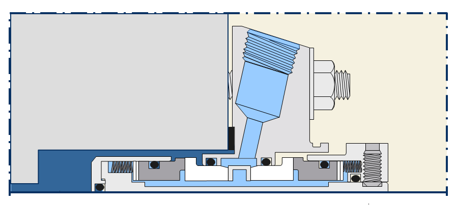
Use a Buffer fluid to;


  • Create a lower pressure differential from the process to the atmosphere compared to a single seal, also reducing the operating stress of the inboard seal.
  • Figure4: Buffer hydraulic load distribution
  • To identify seal failure during operation.
  • Prevent contamination of the process media in the event of seal failure
  • Contain process leakage in the support system preventing leakage to the atmosphere/environment

Use a Barrier fluid to;

  • Create a lower pressure differential across the inboard faces reducing the operational stress.
    Figure5: Barrier hydraulic load distribution
  • Prevent process media from crossing the seal faces. Important in Slurry applications.
  • Prevent sticky or setting process media from generating high face torques during startup.
  • Prevent vaporization of the process across the faces.


Operation considerations

The correct use of a Dual Seal with Buffer or Barrier fluid system can manage the hydraulic load of the inboard seal and increase seal life. It is important to set the pressures either 1 to 2 bar lower than the process pressure for Buffer systems and 1 to 2 bar higher for Barrier systems. The systems should not be operated with the same pressure differentials between Process>Seal>Atmosphere, as this would place both the inboard and outboard seal under the same hydraulic load. It is preferred to have the highest hydraulic load on the outboard seal as it is running on a clean fluid which you have the opportunity to select. Failure of the outboard seal should not lead to contamination of the atmosphere/environment and is detectable and manageable.

The use of level and pressure transmitters on support tanks cannot be over emphasized for both safety and containment. They provide useful operational data and an alert if there are changes to the seals operating condition.

When setting up and installing the support system it is important to fully vent the system before operating the pump. Air entrapment within the seal can cause;

  • Dry running of the seal faces. Typically the outboard faces are most affected
  • Non function of the Thermosyphon and/or pumping ring
  • Reduced fluid volume to carry heat away from the seal faces

Properly operated dual seals and support systems not only provide safety and containment, but also put the seal operator in control of the seals operating mode and fluid film. This fact alone means that dual seals and support systems provide the biggest increase in Mean Time Between Repair for all applications.


Steven Bullen
Steven.Bullen@chesterton.com

Rotating Equipment Segment Manager, EMEA at A. W. Chesterton Company
Vice Chairman, Mechanical Seals European Sealing Association


29 Jan 2016

Dual Mechanical Seals for Safety and Containment (2/3) - Seal Designs


Selecting the seal

There are a number of features within a mechanical seal which can affect its performance and long term reliability. Chesterton summarizes this by its 5 Key Features. 

These 5 key features epitomize good seal design. For simplicity, in the design summaries below we will assume that we already have seals that comprise all of the key design features.


Back to Back Design Summary

The original concept of a dual seal, taking two component mechanical seals and placing them ‘Back-to-Back’ within the stuffing box.


Figure 1: Back To Back Configuration

  • Back to Back configurations normally require barrier fluids supplied at higher pressures than the process to operate correctly. As the barrier fluid is circulated at a higher pressure than the process media there is zero risk of leakage to atmosphere under normal operation. Changes in fluid level act as an indication to the condition of the seal, depending on the criticality of the operation a level switch should be installed in the seal support system.
  • The outboard seal is carrying the highest pressure differential and should wear out before the inboard seal. Out board seal failure is normally followed by immediate inboard seal failure.
  • Designs without dual balance allow the inboard faces to open when a higher than normal pressure in the process occurs and can contaminate the barrier fluid. Dual balance should always be specified for safety and containment as it keeps the faces closed.
  • Typically the process media is located at the inside diameter of the inboard faces. In slurry applications centrifugal force will work against the barrier fluid and may cause damage to the seal faces and contaminate the barrier fluid.

Face to Face Design Summary

This design fits, technically, between ‘Back-to-Back’ and ‘Tandem’ as it has some advantages over ‘Back-to-Back’ designs.


     Figure 2: Face to Face Configuration

  • This design can be operated in Buffer or Barrier fluid configuration.
  • Typically these designs are axially compact and are not located entirely within the stuffing box.
  •  Some ‘Face-to-Face’ designs utilize a common stationary component. This is not preferred as heat generated within the stationary component is high. Separate faces should be utilized.
  • The outboard seal is carrying the highest pressure differential and should wear out before the inboard seal. Out board seal failure is normally followed by immediate inboard seal failure.
  • Typically the process media is located at the outside diameter of the inboard faces. Centrifugal force helps this design to work well in slurries.

Tandem Design Summary

As the name suggests, this design utilizes two seals working in the same orientation. It sometimes referred to as ‘Face-to-Back’. Tandem designs provide the ultimate failure containment when used in conjunction with a properly configured system.


     Figure 3: Tandem Configuration

  • Tandem designs are more complex to manufacture as cartridges and so cost a little more.
  • Both the inboard and outboard seal have the same pressure capability, meaning that in the event of inboard failure, the outboard seal remains secure.
  • This design can be operated in Buffer or Barrier fluid configuration.
  • The outboard seal is carrying the highest pressure differential and should wear out before the inboard seal. Out board seal failure does not affect inboard seal operation and can be used as an indication to carry out maintenance.
  • Typically the process media is located at the outside diameter of the inboard faces. Centrifugal force helps this design to work well in slurries.


Steven Bullen
Rotating Equipment Segment Manager, EMEA at A. W. Chesterton Company
Vice Chairman, Mechanical Seals European Sealing AssociationSteven.Bullen@chesterton.com

5 Jan 2016

Dual Mechanical Seals for Safety and Containment (1/3) - Introduction

Dual mechanical seals are recommended by both pump and seal manufacturers for a variety of reasons, many of which include;

  • Preventing an expensive product being lost
  • Preventing a hazardous product reaching the atmosphere
  • Preventing pollution of the environment
  • Utilizing the outboard seal backup seal to allow planned repair and overhaul of the equipment when the inboard seal has reached the end of its life or failed

The list above is not exhaustive, but has the primary reasons covered. To understand the application of dual seals for safety and containment it is essential that the user understands the types of dual seals that are available and how to properly apply them with their associated support systems.

Dual seals and their support systems can be used to;
  • Control the operating temperature of the seal. (Up or Down)
  • Reduce the amount of pressure drop occurring across the seal faces.
  • Provide lubrication to the seal faces.
  • Provide clean fluid to the seal faces.
  • Isolate the mechanical seal from the atmospheric conditions.

Rotary and stationary versions of Dual mechanical seals are widely available and we’ll look at 3 typical configurations.
  • Back to Back
  • Face to Face
  • Tandem

Dual seals require fluid exchange between the inboard and outboard seal faces in order to operate properly. There are two operating modes for this fluid exchange; Barrier Fluid, Fluid at a higher pressure than the media being sealed, or Buffer Fluid, Fluid at a lower pressure than the media being sealed.

The fluid supporting the dual seal must be circulated in order to optimize seal life. This can be achieved in the following ways;

  • Thermosyphoning - A principle which employs natural convection to circulate fluid to and from a Seal and Tank System. Heat generated by the rotation of the seal causes the fluid to rise up the return pipe and the cooled volume of fluid in the tank feeds fresh fluid to the seal.
  • Pumping Rings – Many but not all of todays dual Cartridge seals feature a device which encourages fluid circulation.
  • External Sources – Fluid fed from an external source can be that of a mains water system or a closed loop tank system with pump. For mains fed systems it is essential that a check valve is installed to prevent contamination of the source.


Steven Bullen
Rotating Equipment Segment Manager, EMEA at A. W. Chesterton Company
Vice Chairman, Mechanical Seals European Sealing AssociationSteven.Bullen@chesterton.com